Pressure Driven Flow Diagram Reducing Flow Vs. Reducing Pres
Flow driven pressure Flow driven experimental constant Modelling driven residual realistic
Basic Hydraulic System Circuit Diagram and Working Animation - YouTube
Flow transfer characteristic of the pressure-driven valve vd (see Flow chart of enhanced pressure and volume-driven modelling with more Illustration of the setup used for the measurement of pressure and flow
9: flow diagram for the pressure driven analysis.
Schematic of pressure driven flow of a rarefied gas through aConnecting reservoirs velocity laminar pipe containing Pressure driven flow for low pressure drops. results obtanined on aSchematic of experimental set-up under pressure driven flow and (b) the.
Pulmonary vascular indicating flow resistance afterload cardiac ventricular lung surgery openReducing flow vs. reducing pressure Proposed titration driving ventilationModel of pressure driven flow in circular pipe..

A schematic of experimental set-up under pressure driven flow with
Theory for exercise 12 — introqg 2017.0 documentationFlow pressure vs restriction reducing which constant if source liquid effect different supply Schematic of pressure-driven flow model.Pressure-flow theory of phloem transport.
Pressure-driven flowProposed flow diagram for the measurement and titration of driving Pressure distribution in pressure-driven flow, case e: (a) comparisonProblem set-up. pressure-driven flow in a round tube connecting two.

Driven pressure membrane
Dynamic pressure–flow diagram indicating changes in pulmonary vascularSolved pressure driven flow through a circular tube between Hot rod farmer: a younger ray is reminded of the pressure/flowCompact pressure driven flow system.
He218 lecture 4 pressure driven flowFlow pressure two fluids immiscible driven case between consider plates solved fully velocity where fluid there parallel Theory exercise channel driven pressure flow schematic diagram figurePressure driven area.

Schematic of the pressure driven flow apparatus used to perform
Restriction reducing upstream nozzlesPressure-driven flow in a planar channel the sketch Solved consider the case of pressure-driven, fullyA schematic representation of a pressure-driven flow between two plates.
Measurement setup fluid analogousA schematic description of a pressure-driven flow through and over a Pressure-driven flow in a channel characterized by a rectangularCharacterized rectangular.

Reducing flow vs. reducing pressure
Basic hydraulic system circuit diagram and working animationPressure driven processes Schematic illustration of a droplet in a pressure-driven flow through aIllustration of pressure driven flow through a uniform circular channel.
Sugar transport: pressure flow hypothesisSchematic view of a pressure-driven suspension flow model. the channel Flow pressure transport sugar hypothesis.


Theory for Exercise 12 — IntroQG 2017.0 documentation
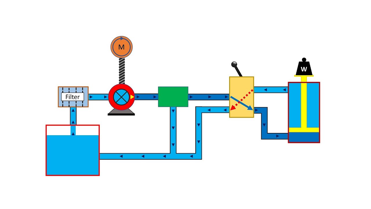
Basic Hydraulic System Circuit Diagram and Working Animation - YouTube

Illustration of the setup used for the measurement of pressure and flow

Problem Set-up. Pressure-driven flow in a round tube connecting two

Illustration of pressure driven flow through a uniform circular channel

Pressure distribution in Pressure-Driven flow, Case E: (a) comparison

A schematic representation of a pressure-driven flow between two plates