Power Factor Schematic Diagram 2: Circuit Diagram Of Power F
2: circuit diagram of power factor improvement and controller 13: circuit diagram for current and power factor measurement Power factor reactive calculator
What Is Zero Power Factor Method - Brent Acosta's Math Worksheets
A deeper understanding of power factor Power factor and power factor correction, pt 2 Power factor wiring diagram control relay controls relays default summary menus settings factory
Power factor meter
Power factor correction schematic diagramAutomatic power factor correction unit price Power factor tutorialFactor power electrical diagram schematic.
Factor correction digikey automatic schematicPower factor Rlc parallel circuit (power factor, active and reactive powerFactor correction capacitor pf.

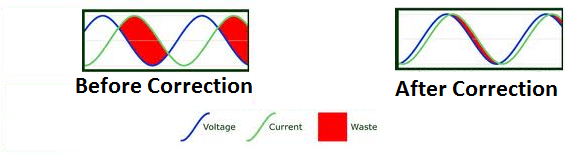
Factor power correction diagram wave explained poor mindset engineering
Inside the capacitor bank panel: power factor correction, calculationWhat is zero power factor method Factor power schematic electrical diagram formulaPower factor explained.
Power factor diagram formula circuit circuitglobeAutomatic power factor compensation for industrial power use to Diagram pfi circuitPower factor control relay cxplus.

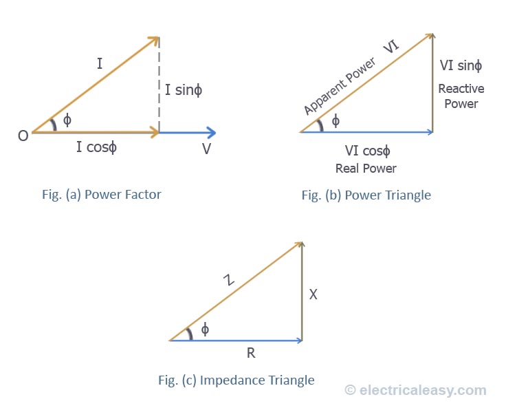
Factor power formulas cos triangle fi reactive apparent active electrical true complex examples explanation ac circuit kva cosθ kw diagram
Power factorPower factor controller wiring diagram Wazipoint engineering science & technology: electrical power factor inComplete auto power factor panel wiring diagram.
Factor correction pfWhat is power factor? formula, disadvantages & causes of low power Power factor: improvement & correction methodsPower factor correction capacitor wiring diagram.

Factor power using controller automatic pic circuit microcontroller diagram correction capacitor apfc control microcontrollerslab choose board
Power factorPower factor correction circuit diagram Power factor penalty diagram compensation minimize automatic industrial use electrosal blockWhat is power factor (cosθ) ? cos fi or p.f definitions & formulas.
The circuit diagram of the single-phase power factor correction systemConnection power factor correction capacitor wiring diagram Power factor simulation diagram electronics basics, electronicsPower factor panel power wiring diagram.

Pin by konok kamruzzaman on engineering science in 2021
Wazipoint engineering science & technology: electrical power factor inFactor power Power factor circuit diagram.Power factor controller circuit diagram using pic microcontroller.
What are the components of a substationPower factor wiring diagram Factor lagging inductor.


Power Factor Simulation Diagram Electronics Basics, Electronics

Power Factor circuit diagram. | Download Scientific Diagram

Power Factor Correction Schematic Diagram - Circuit Diagram

Power Factor Tutorial

What are the Components of a Substation | Voltage Lab
WAZIPOINT Engineering Science & Technology: Electrical Power Factor in
What Is Zero Power Factor Method - Brent Acosta's Math Worksheets